[Unreal] GameCube-Style Stencil Lights
Overview
This guide will go over a performant method to replicate toon stencil lights in Unreal, as seen in old-school games. An iconic example is the torches from The Legend of Zelda: The Wind Waker.
In Wind Waker on GameCube, this effect is done using a stencil buffer. A great breakdown of how this effect was probably achieved can be found here in the Hyrule Travel Guide by Simon Schreibt.
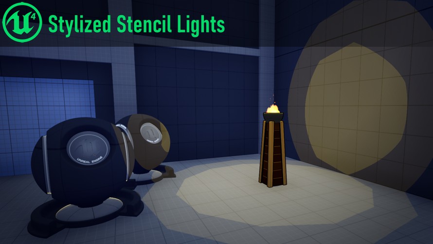
Here’s how ours will look in Unreal:
Caveats
- This method is probably not as performant as the classic GameCube method, but it’s still pretty cheap.
- These lights will draw on the backsides of surfaces too (just like the classic effect; see note at the end).
The Method
For this Unreal implementation, we will be using a different method from the classic effect. You may be tempted to use the stencil buffer and custom depth in Unreal, but they have limitations that prevent us from using them (more on this at the end). It actually won’t be a true “stencil light” at all – just styled like one!
Instead we’re going to implement this effect all within an additive surface material on a sphere.
First, let’s visualize what we want to achieve:
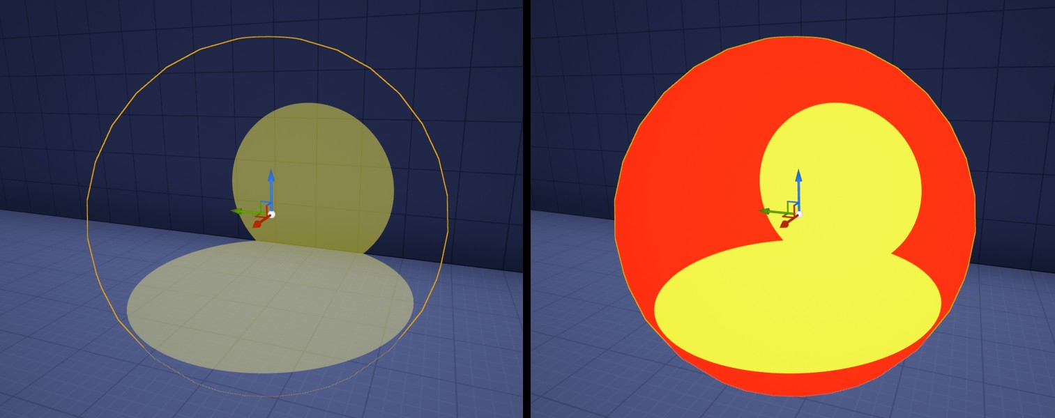
We want to color the pixels over the parts of the environment intersecting our sphere.
Let’s think about the area we’re coloring:
- The pixels we want are all inside the sphere in screen-space.
- Therefore, we can take the sphere’s pixels, and mask out a sub-set of them.
- The parts of the environment we want are inside the radius of the sphere in world-space.
- Therefore, if we can get the world-space position of the environment at a pixel, we can check if it should be colored or not.
Here are the basic steps for our effect:
- Use a sphere mesh.
- Create an additive material with no depth test.
- In the material, get the world position of the environment using the depth buffer.
- Check if that world position is within the radius of the sphere.
And additional steps for more flare:
- Pass additional data to the material with Custom Primitive Data.
- Perform additional math to mask-out polygonal shapes to mimic the old-school look.
- Animate the mask in the material.
Note: Thinking with Pixel Shaders
A quick note on pixel shaders. When rendering a 3D material in Unreal, much of its logic is going to run on the GPU in a pixel shader, which performs the same logic once for every pixel being rendered. Unreal’s material editor abstracts this away from you, but it’s helpful to know what’s happening behind the scenes.
As you build materials like this, think 1 pixel at a time! The logic we write below doesn’t know about the whole screen, just 1 arbitrary pixel.
Also, trig operations (sine, cosine, etc) and square root operations are relatively expensive on the GPU. We can’t avoid them completely, and using a few isn’t the end of the world, but we avoid them when we can!
Part 1 - Basic Setup
Actor Blueprint
First we’re going to make an Actor Blueprint to package up our effect. This will give us a way to tweak settings of individual lights, and pass some extra data over to our material.
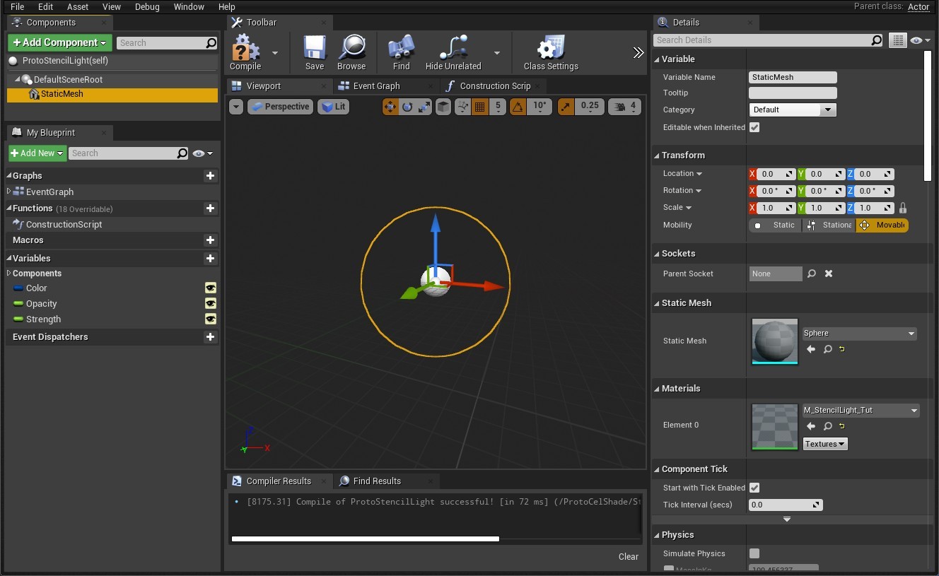
Create a new Blueprint Class, base class Actor. You can call it “StencilLight”.
Do the following to it:
- Add a StaticMesh component. Set it to a sphere model (You can use the default Engine/BasicShapes/Sphere)
- Create a new Material, call it something like “M_StencilLight”, and apply the material to the sphere.
- Add a Linear Color variable called “Color”, pick a default color.
- Add float variable called “Opacity”, default 0.1.
- Add float variable called “Strength”, default 0.5.
- Set all those variables to instance editable (the little eye icon)
Custom Primitive Data
We’re going to add a function to this class that sets Custom Primitive Data on the sphere mesh. This is how we will pass information to our material.
Create a function called “SetPrimitiveData”, call it in your Construction Script.
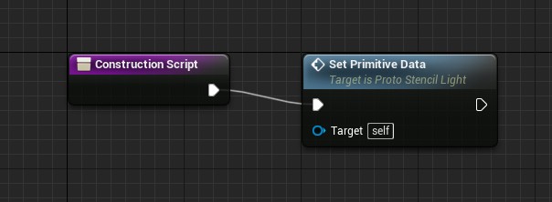
In the function, set the following primitive data:
- Color multiplied by Strength, Vector3 at index 0.
- Opacity, Float at index 3.
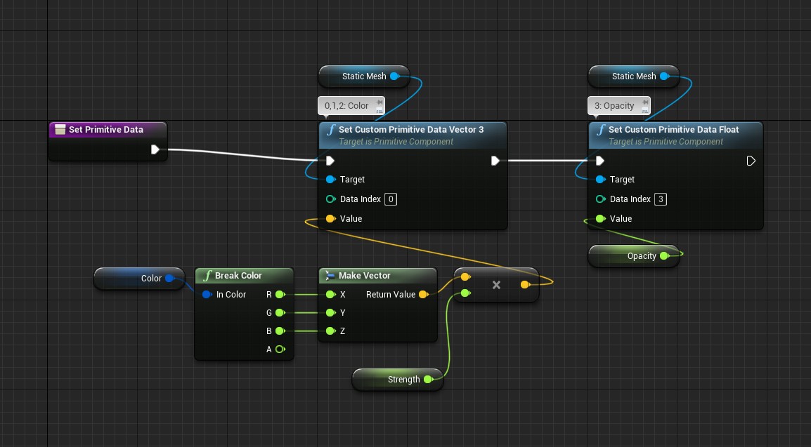
Note that since the Color is a Vector3, it will actually occupy indices 0, 1, and 2 to hold the vector (a quirk of how Custom Primitive Data works.)
Material Setup
Open up your new material and use the following settings:
- Blend Mode: “Additive”
- Shading Model: “Unlit”
- Check the box for Disable Depth Test.
Create parameters for Color and Opacity, and check the box for Use Custom Primitive Data. These will correspond to the data we sent in the blueprint.
Color will use index 0 (since it is 3 channels, it will automatically get 0, 1, and 2). Opacity will use index 3.

plug these parameters into the Emission and Opacity outputs.
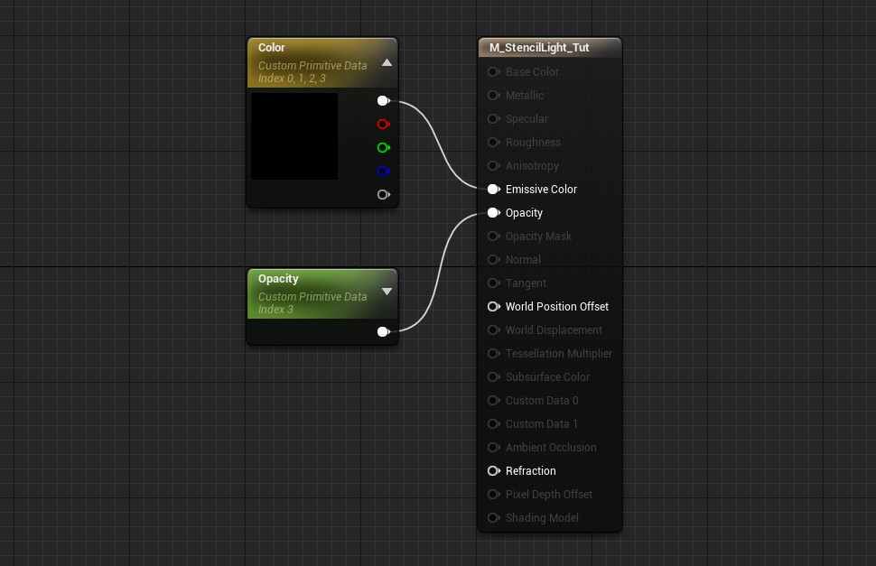
Place an instance of your actor in the level. You’ll have something that looks like this:
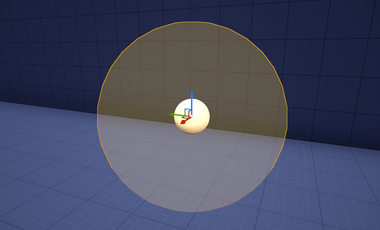
However, if you fly your camera inside it disappears!
To solve that we actually want an inverted sphere, so the material is on the faces on the inside. Ideally, we should create a new inverted sphere mesh. In case you can’t make a new asset, you can simulate this in the material by doing the following:
- Check the box for Two Sided
- Use the TwoSidedSign node to multiply the opacity
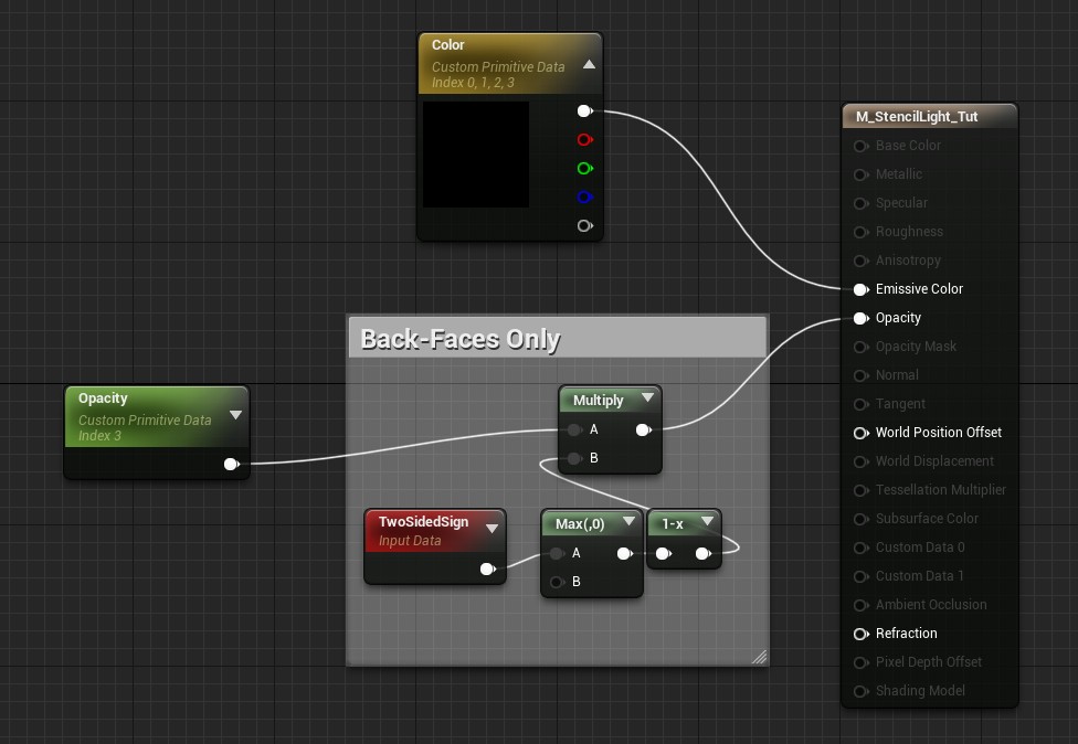
Part 2 - Sphere Mask
Now it’s our job to mask out the pixels we don’t want.
To do so, we’re going to create some material functions. To create a material function, right click in the content browser, and navigate to Materials & Textures > Material Function.
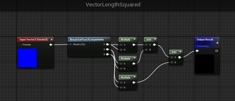
VectorLengthSquared
We’re going to do a distance check, and finding the length of a vector requires a square root operation. This is a bit expensive, so instead let’s make a function to get the squared length of a vector, so we can compare squared distances and avoid a square root.
WorldPosFromDepth
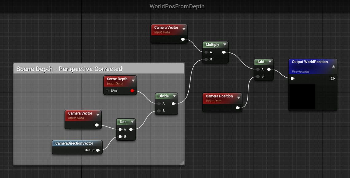
WorldPosFromDepth will do the heavy lifting of the material. It is going to use the Depth Buffer to find the world position of the environment for the pixel being rendered.
We can do this because our additive material causes the sphere to not get written to the depth buffer.
Here are the built-in nodes we’re going to use to make this logic:
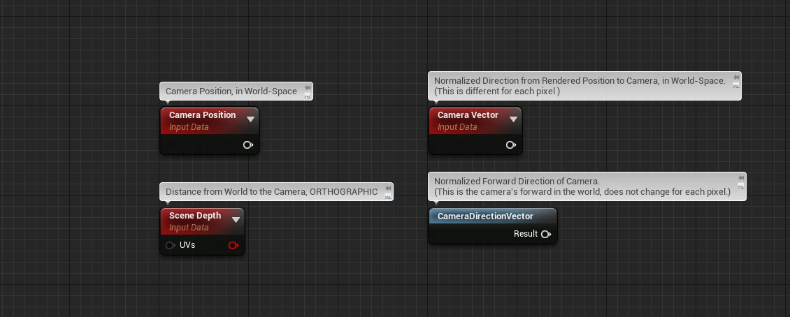
It takes some basic vector math to get the world location from this. We start at Camera Position, and travel Scene-Depth units down the inverse of the Camera Vector. In other words:
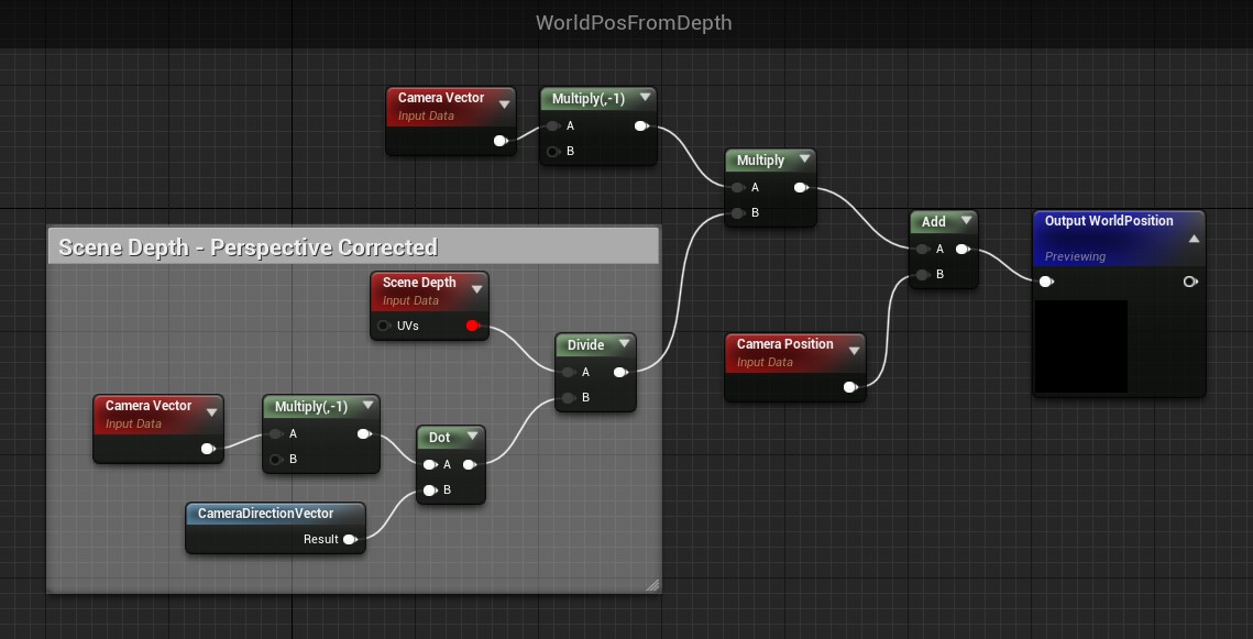
Camera Position + ( Camera Vector * -1 * Scene Depth )
However! Scene Depth is orthographic, but our camera has perspective. We need to modify the depth value first.
To do so, we have to use the CameraDirectionVector. I’m going to spare you the trigonometric gymnastics of vector projection here. It works out that you can transform the Scene Depth value into the corrected value with a dot product and a division.
Here’s all that vector math implemented in nodes:
As a bonus, you can also get rid of those two multiplications by -1, since they cancel each other out. Giving us our final function:
Putting it Together
Now that we can get the World Position at a pixel, all we have to do is compare it with the sphere’s origin to see if it is inside the sphere!
The built-in Object Position and Object Radius nodes are convenient here (Although we should shrink the radius slightly so that the polygons of the sphere don’t clip our effect.)
As a reminder, we’re going to compare distance-squared as an optimization. Subtracting Object Position from WorldPosFromDepth gets us a vector between those two positions. We get the squared-length of it, compare it with the squared Object Radius, and if it’s less it must be inside the sphere.

With that implemented, you now have a fully-functioning spherical stencil light. You can tweak the color, strength, and opacity in the object’s Details Panel.
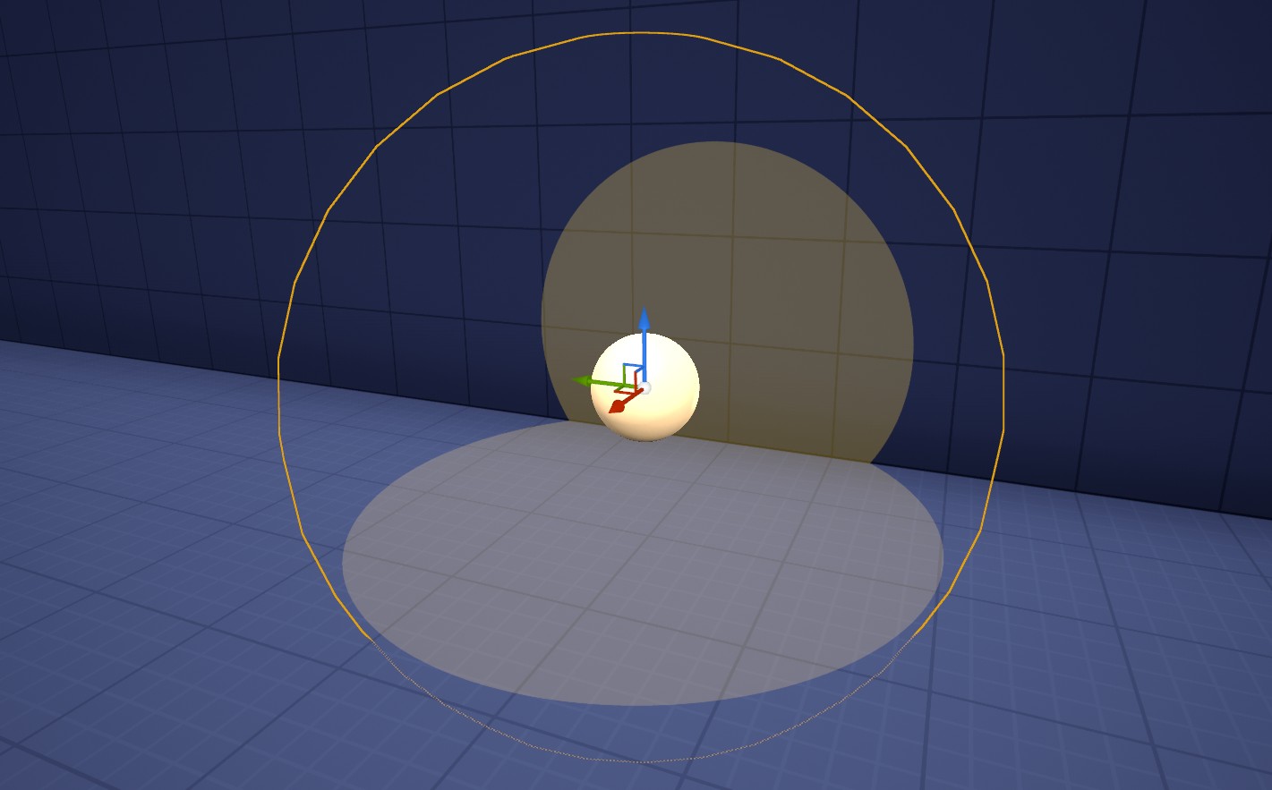
Part 3 - Polygonal Mask
A spherical light is nice, but it looks pretty modern. Next let’s get fancy and mask out polygons to complete the old-school GameCube-era look.
The trick is, we have to mask this out mathematically – we can’t test against an actual polygonal mesh. This is quite difficult to do in 3 dimensions. I’m afraid masking-out an arbitrary 3D poly sphere requires a level of math beyond my skills.
Instead, let’s simplify the problem and mask out polygons in just one axis. This will look great most of the time, and still provide some visual interest on glancing surfaces.
Note that this mask is going to be the most computationally expensive part of our material!
The Algorithm
Let’s think through how this will work. Let’s work in the Z (Up) axis, so when the sphere is upright, we mask out polygons on the floor.
We’re going to support N sides in this algorithm (the number of side will be tweakable.) For now let’s imagine we are using 8 sides, and we’re looking down at our sphere from above:
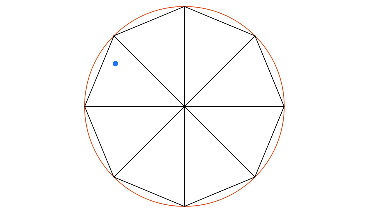
The red circle is the sphere, the blue dot is the test position. The black lines are the imaginery triangles that make up our 8-sided poly circle.
The question is: Is our test position inside the poly circle?
There are a few ways to solve this, and we’re going to walk through a simple one. Let’s compare our test position with the nearest vertex of the poly sphere, and consider these two angles:
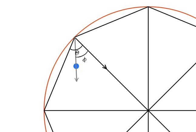
We can see in this example that the test position is indeed inside the poly sphere, and Φ is less than Θ. If the test position were outside, Φ would be greater than Θ. Voila! If we find these two angles, we have our answer.
Θ is easy to find. Our poly sphere is made up of triangles. If our poly sphere has N sides, the angle between each vertex from the center will be (360/N). The remaining two angles of each triangle are equal. Therefore, we know that Θ must be (180 - (360/N))/2.
Φ requires a bit more effort to find. We’ll need to get the direction vectors of the two lines making the angle. Finding the direction of the gray line will require calculating the position of the nearest vertex. Once we have these two directions, we can calculate the angle between them, giving us Φ.
There is one other problem to solve, consider this side view:
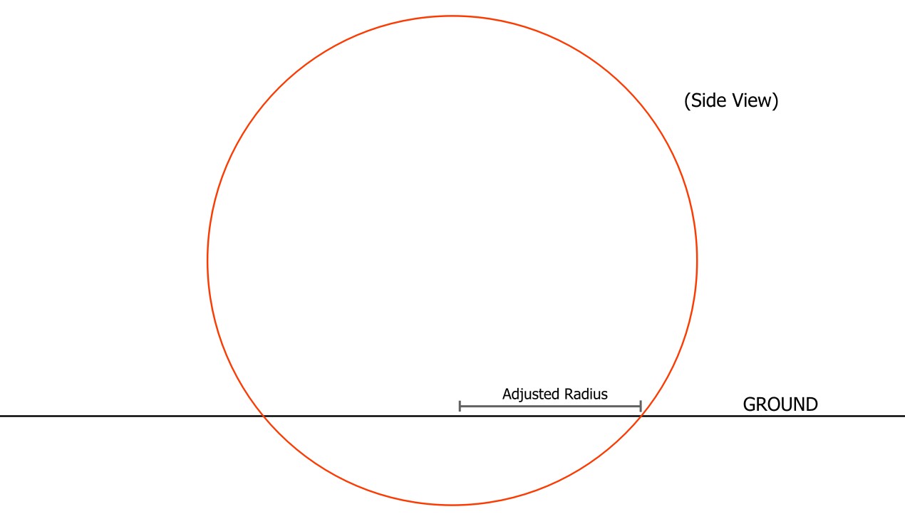
We want our polygonal mask to create visible polygons regardless of how deep the sphere is in the ground. To do this, we need to know the radius of the circle where the sphere intersects the world
For a given world position, we will imagine a plane at that position orthogonal to the sphere’s up axis. We will solve a sphere-plane intersection and get the radius of the resulting circle.
Alright, that’s the bulk of the math we need. Now let’s implement the effect.
Modify the Blueprint
First let’s add more variables to our Actor Blueprint
- bool - UsePolygonalMask, default false.
- int - PolyMaskNumSides, default 8.
- float - RandomSeed, default 0.
Next, in our “SetPrimitiveData” function let’s pump more data through with Custom Primitive Data:
- UsePolygonalMask, bool at index 4.
- PolyMaskNumSides, int at index 5.
- The Actor’s Forward Vector, Vector3 at index 6.
- RandomSeed, float at index 9.
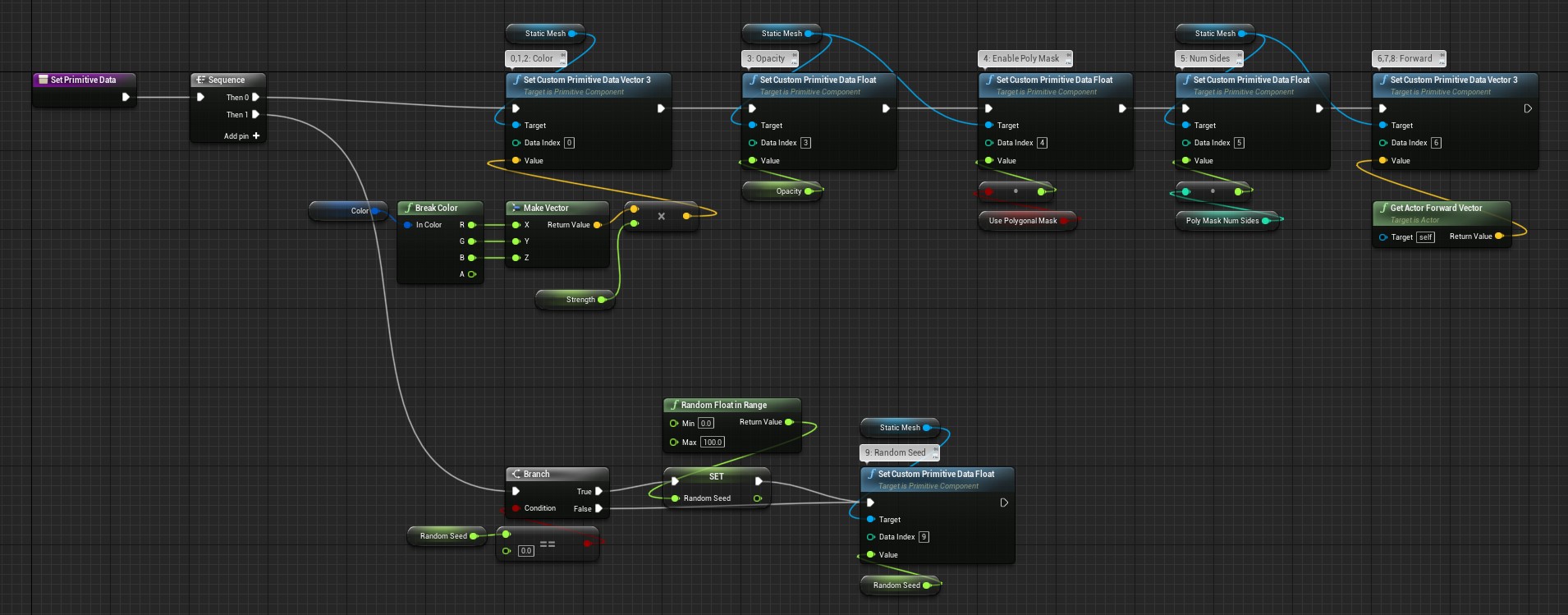
The one unusual thing here is the RandomSeed. We randomly generate a new float if it’s at its default value of 0. This means the user doesn’t have to set it themselves (but they can if they want), and it will stay consistent for this object after it is constructed once.
More Material Functions
The bulk of our new logic will take place inside of new material functions. Let’s make them now.
IsPointInsidePolyCircle
This the implementation of our math problem to determine if a point is within a 2d poly circle.
This is implemented relative to a forward direction and a normal for the circle, as if it were on a plane. It will return 0.0 or 1.0 depending on if the check passes.
This is a long one, but there are no big surprises compared to the conceptual breakdown above.
(You can right-click and open this image in-full)

SpherePlaneIntersectionRadius
This function implements the second math problem, to get the radius of the circle where our sphere intersects the world.
We’re going to use the radius this returns when we call IsPointInsidePolyCircle.
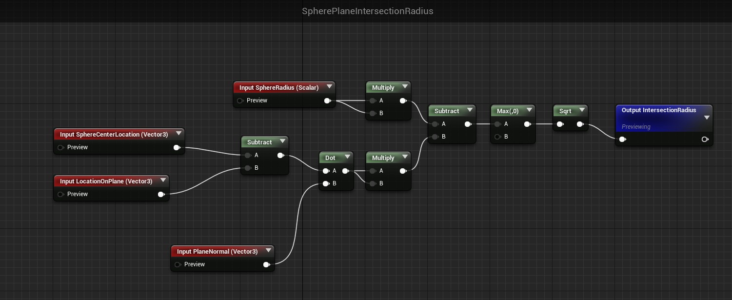
ZAxisPolyCircleMask
Here is where we’ll combine the two above functions. This is what we’ll call directly from our material.
It performs the poly circle check, using the modified radius.
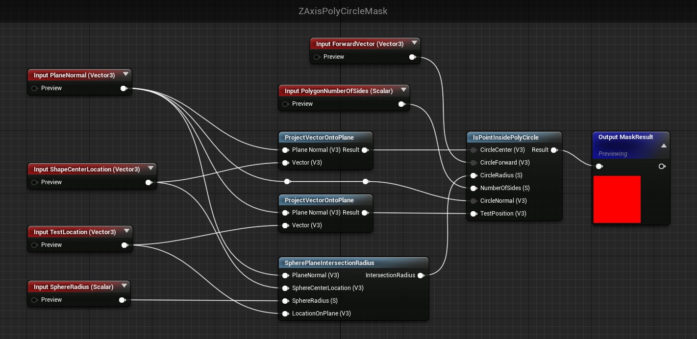
Putting it Together
Now it’s just a matter of calling our new function with the right parameters. We’ll format our material so that we branch between the simple sphere mask, or the poly mask.
Remember that when you add the new parameters, you must check the box for Use Custom Primitive Data and set the matching index from the blueprint.

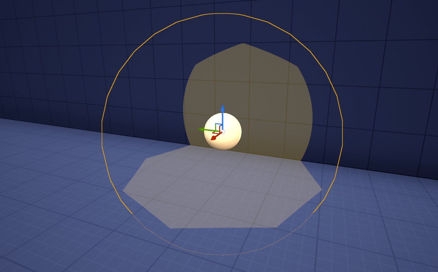
Now you can enable your poly mask on your stencil light in the level, and get something like this:
You can also rotate it, and the mask will align with the actor’s Z axis. Useful if for example you want to place it on a wall.
Part 4 - Animation
Finally, we’re going to make our light move and flicker like a torch.
We’re going to do this in the material, by modifying the variables we pass into our functions over time.
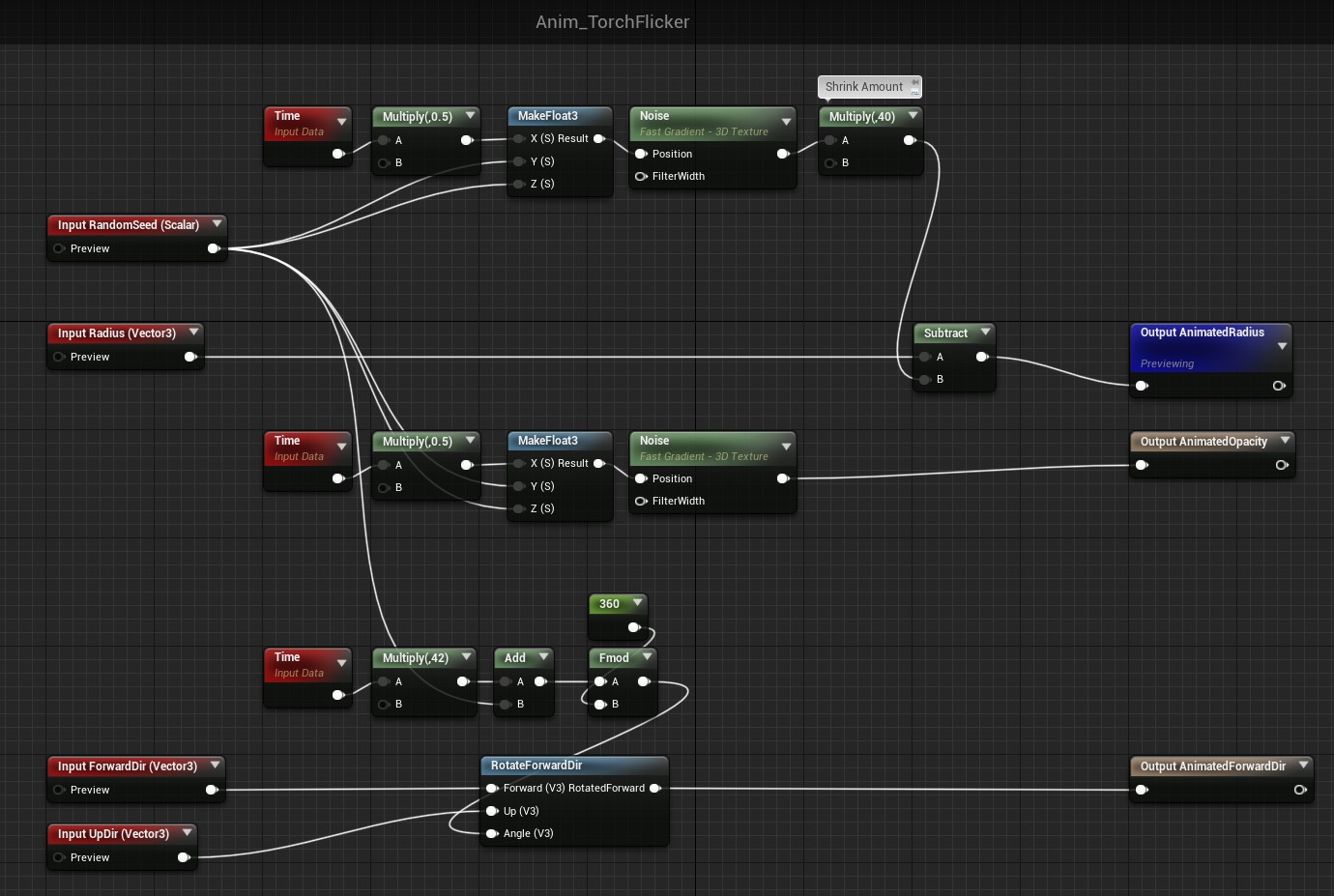
We want to do 3 things:
- Wiggle the radius in and out.
- Rotate the spherical mask.
- Fade the opacity in and out.
We’re going to do this in, you guessed it, a couple material function:
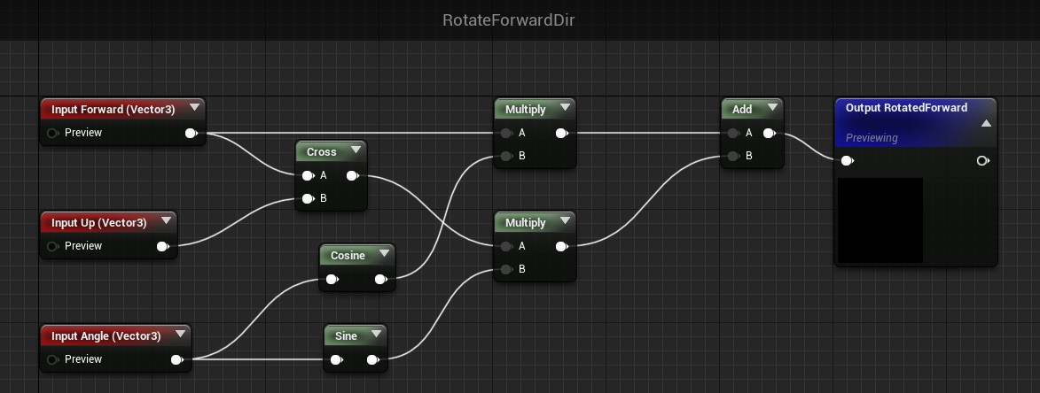
RotateForwardDir
We’ll start with a helper function for rotating our mask. The mask will rotate if we adjust the Forward Direction, and this function will do that for us.
Anim_TorchFlicker
This is the function we’ll call from our material. It does the 3 animations outlined above, and uses the RotateForwardDir function.
This is where we use our RandomSeed variable. It will offset the animation for each light in the scene.
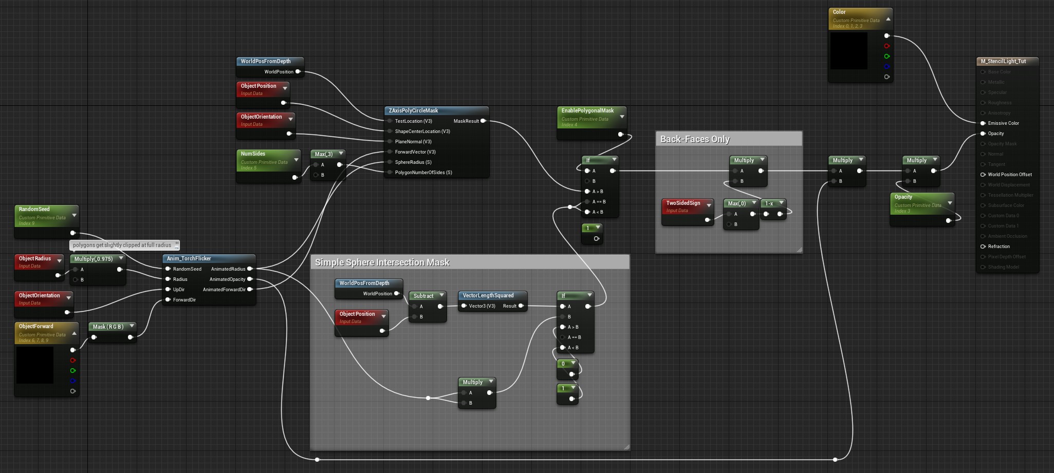
Putting it Together
Finally, here it is hooked up in our material. The material functions just like it did before, but now we modify some parameters first.
Congrats! Here is our final light:
Final Thoughts
Now you can go nuts and put them all over the place.
Experiment with new animations to create new looks. Fireflies? Light from a television?
Or try modifying the math for the mask. Maybe mask out an oval or a cone to make new types of lights.
Custom Depth (Why We Didn’t Use It)
Why didn’t we use Unreal’s custom depth and a post process material to mimic the Wind Waker method above?
The problem is when we have multiple lights, we need to be able to process pixels for each stencil light independent to other ones. If there is more than 1 light, there are cases where their spheres will overlap (in the world, or on the screen), and a post process material reading custom depth will not give us enough information in these cases. Whichever sphere is closer to the camera stomps info about the other.
If we had a way to write a custom value to a stencil buffer per-pixel, we could get around this. But unfortunately this is not something Unreal exposes to us (unless we make our own modifications to the engine.)
Prevent drawing on backsides
As mentioned at the beginning, this effect will also draw on the backsides of surfaces. I.E. if it’s casting light on a thin wall, the backside of the wall will be lit too. This is exactly how the old effect on Gamecube worked.
If you’re using Deferred Rendering in Unreal, you can mitigate this with an extra calculation if you like. You can use a Scene Texture node with “WorldNormal” selected, and use a dot product between that and the direction from the center of the sphere to WorldPosFromDepth. This won’t fix all artifacts, and it doesn’t always look better, but you might find this useful.
Performance
Some more notes and tips about performance.
Overdraw
This effect causes overdraw, which is when you take a pixel you’ve already rendered, and then perform more rendering calculations on it. There’s no way around this with this kind of effect (even if we could use the stencil buffer). The extra calculations we’re doing are fairly cheap, but it’s an extra cost nonetheless.
“If” Nodes
Another important note is that if nodes in materials will still run both branches. The polygonal mask and its animation adds a measurable cost to this material, even if you don’t choose to enable them! You can avoid this extra cost by:
- Using static switch nodes to separate logic (and enabling/disabling them in material instances).
- Or, dividing this into multiple materials that only include the logic you need.
In either case, you’d need to select different materials or material instances for different lights. This makes them less flexible, but more performant.
Noise Nodes
In the animation section we used a Noise node. Even with the “Fast Gradient” setting, this is a fairly expensive node. You could improve performance further by creating your own noise texture, and sampling it instead.
Cost While Obstructed
Since this material disables the depth-test, it will always try to draw anywhere on the level, even if fully obstructed. This means you’re still paying a cost for ones you can’t see. This might be fine (Wind Waker simply pays the cost all the time on Gamecube), but you may consider manually disable these when they are out of view.