[Unreal] Ignoring Morph Target Normals, Transfering Normals
Overview
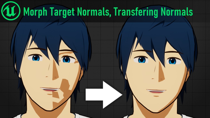
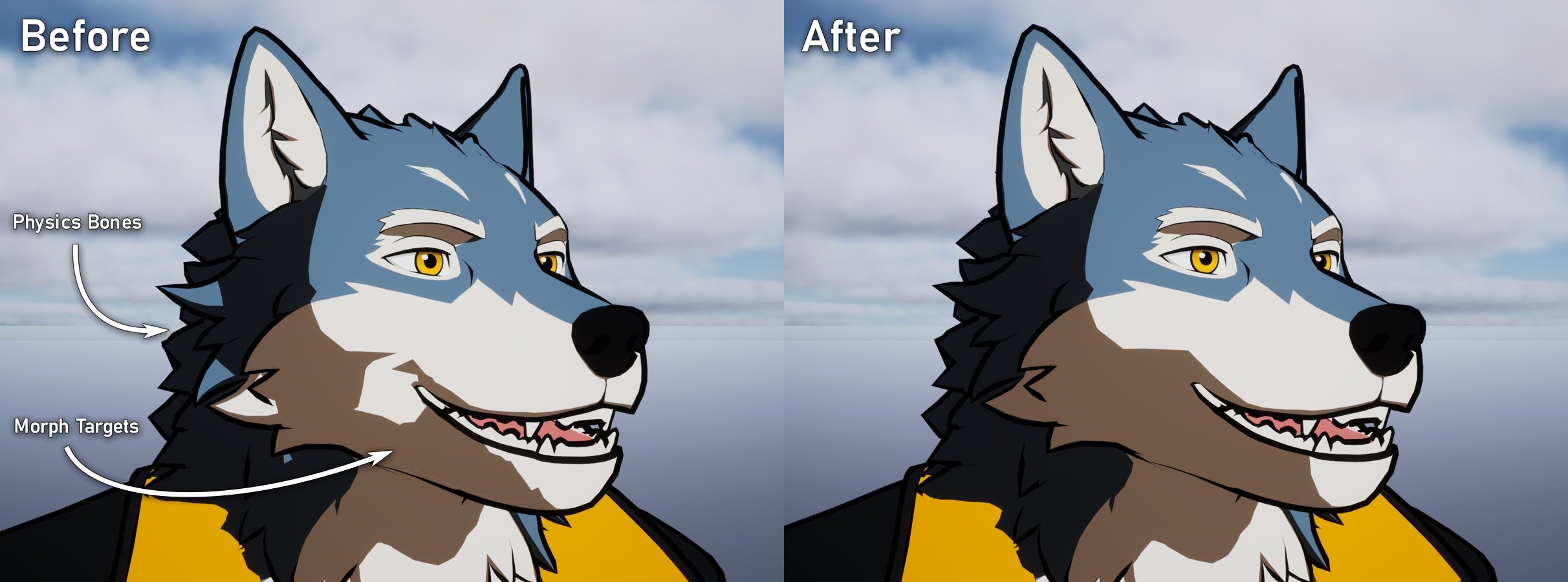
If you’ve tried to make cel-shaded, anime, or stylized characters in Unreal you may have run into issues with ugly shadows. Especially, issues with Morph Targets (aka Blendshapes, shapekeys) and physics bones distorting normals and creating undesireable lighting.
This is especially a problem with cel-shaded art styles with hard shadows, which can become very distorted when a mesh’s surface normals deform. For example on this character:
This guide shows how to fix these issues using Unreal 5’s Deformer Graph feature.
Two Methods
In this guide we’ll create two methods for controlling your mesh’s normals:
Ignore Morph Target Normals
This method ignores morph targets when calculating the mesh’s final normals.
This is very useful for characters with morph target based facial animation, especially toon and anime style characters.
This method should be performant enough to use in most games
Transfer Normals Between Identical Meshes
This method is more expensive, transfering all normals from one (identical) mesh to another. This is used with a hidden duplicate of a skeletal mesh that animates alongside the visible mesh.
This allows fixing trickier issues, such as physics bones manipulating normals. It’s similar to using a “Data Transfer” modifier in Blender.
This method is more expensive, and may not be suitable for all games. Proceed with caution and profile your performance!
Part 1 - Enable the Deformer Graph Plugin
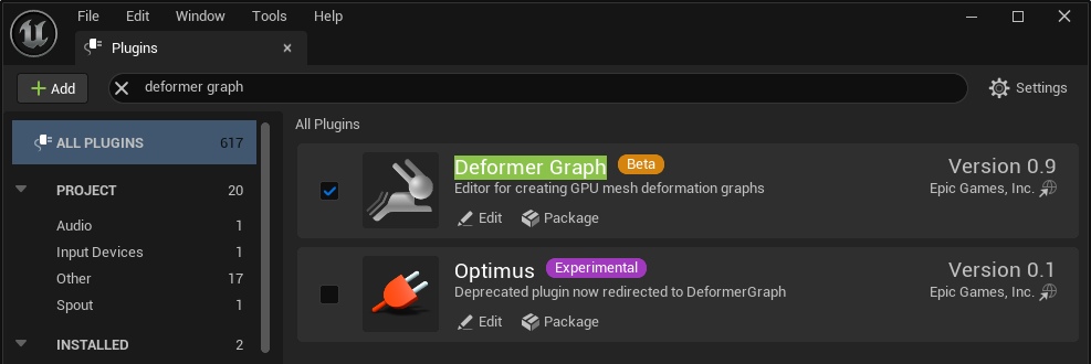
Before continuing you must have the Deformer Graph plugin enabled in your Unreal project.
To do-so, in the top-left of the main Editor window navigate to Edit > Plugins. Then in the window that appears, search for “Deformer Graph” and enable the plugin (if it is not already enabled).
How Does the Plugin Work?
The Deformer Graph plugin allows you to use custom HLSL vertex shader code to influence the look of a Skeletal Mesh.
The workflow is as follows:
- Create a “Deformer Graph” asset, containing a node graph and HLSL shader code.
- On a Skeletal Mesh, set the “Mesh Deformer” parameter to the Deformer Graph asset you created.
Note: while Deformer Graphs involve HLSL code, this guide does not assume any prior coding knowledge.
Part 2 - Ignoring Morph Target Normals
We’re going to make a new Deformer Graph asset to create the “Ignore Morph Target Normals” feature.
However, let’s copy an included example graph instead of writing one from-scratch. In the Content Browser, select the root “All” folder and search for “DG_” to find the Deformer Graphs included in Engine Content.
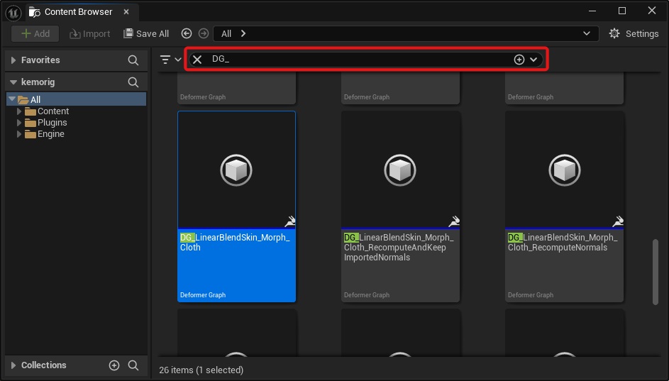
Find DG_LinearBlendSkin_Morph_Cloth, copy it, and paste into your project’s Content folder.
Let’s name the copy DG_ExcludeMorphTargetNormals
If you can't find any Deformer Graph assets when searching, make sure "Show Engine Content" is enabled in the Content Browser Settings.
Overview of the Graph
Let’s go over how our Deformer Graph works. Open your Deformer Graph asset.
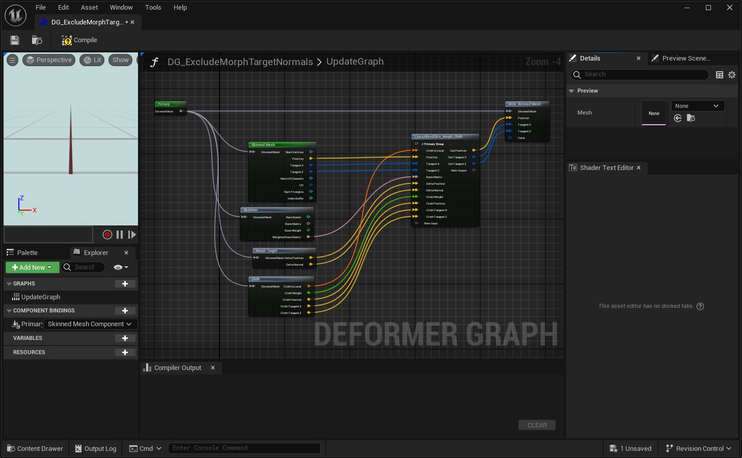
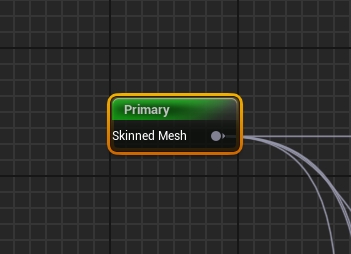
We can see that the input is a Skinned Mesh named “Primary”. This is the mesh that has the Deformer Graph asset applied to it.
Note that "Skinned Mesh" is a parent class of "Skeletal Mesh", so this graph can run on any Skeletal Mesh.
Now look at the output (“Write Skinned Mesh”).
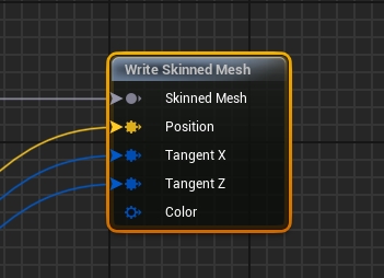
Whatever you pass into the Write node overrides the look of the mesh, and if a pin is not connected it will not be overriden. For example, if you don’t pass anything into “Position”, then the Deformer Graph will not affect the mesh’s vertex positions.
“Tangent X” and “Tangent Z” define the mesh’s normal at a given vertex.
Now select the “LinearBlendSkin_Morph_Cloth” node.
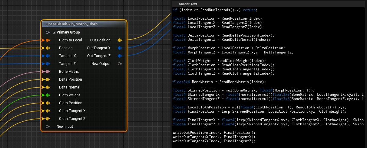
This is a “Custom Kernal Node”. It was created inside this Deformer Graph and it is where custom logic is defined. You will see that this node contains HLSL shader code, and has various input and output parameters defined.
Explaining HLSL is out of scope for this tutorial, but by looking at the Shader Text panel you can see what the node is doing:
- Information from the Skinned Mesh is passed in.
- Linear algebra is performed to calculate a final Position, Tangent X, and Tangent Z (Remember that the tangents define the Normal of the vertex).
- The node outputs the final values.
Modify the Graph
Making this graph ignore morph target normals requires one simple change.
Disconnect the input into “Delta Normal” on the “LinearBlendSkin_Morph_Cloth” node.
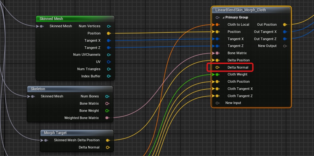
A delta means the difference between one thing and another. In this case, the difference between the mesh’s default normals and the normals with morph targets applied. When we disconnect this pin, this causes a delta of (0,0,0) to be used for morph target normal calculations, nullifying their impact on the final normals.
Compile and save the Deform Graph, and you’re done!
Use the Graph on a Skeletal Mesh
To use your new Deformer Graph on a Mesh, open the Skeletal Mesh asset, look at the Asset Details panel, and set it as the “Default Mesh Deformer” parameter.
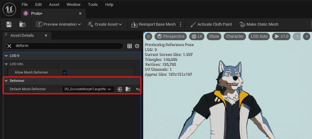
Now, whenever this mesh is used it will run our new Deformer Graph.
You can also enable the Deformer Graph by:
- Adding it to the properties of a Skeletal Mesh Component in an Actor.
- Adding it to a Skeletal Mesh Component at runtime via Blueprint or C++ with the SetDeformerMesh function.
Part 3 - Transfering Normals Between Meshes
Now we’ll make a Deformer Graph for the second feature: transfering normals from one mesh to another identical mesh.
Make a copy of your Deformer Graph from Part 2, and name the copy DG_TransferNormals.
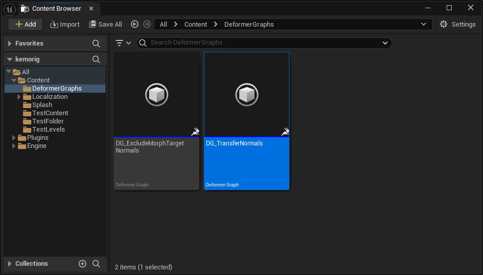
Open DG_TransferNormals.
Overview
This graph will be a little more complicated; here is an outline of how it will work:
![]()
- We will input a second mesh into the graph (the mesh we will transfer normals from)
- Our old Kernel Node logic will be split: position and normal calculation will be in 2 different nodes.
- We will use a 3rd Kernel Node to transfer the normals from the second mesh to the primary mesh.
Let’s get started.
Add a Component Binding
This graph needs to know about a 2nd mesh in order to work, and we do this by adding a “Component Binding.”
Component Bindings are inputs into our Deformer Graph. We actually already have one: the mesh running the Deformer Graph is the "Primary" binding.
Additional Component Bindings work like this:
- When an Actor has multiple Skeletal Mesh Components, a Deformer Graph on one of them can map the others to Component Bindings.
- The Deformer Graph maps meshes to bindings by using Component Tags. We assign a Component Binding a tag, and if a Skeletal Mesh Component in an Actor has a matching tag, it will map to the binding and be passed into the Deformer Graph.
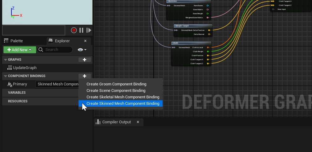
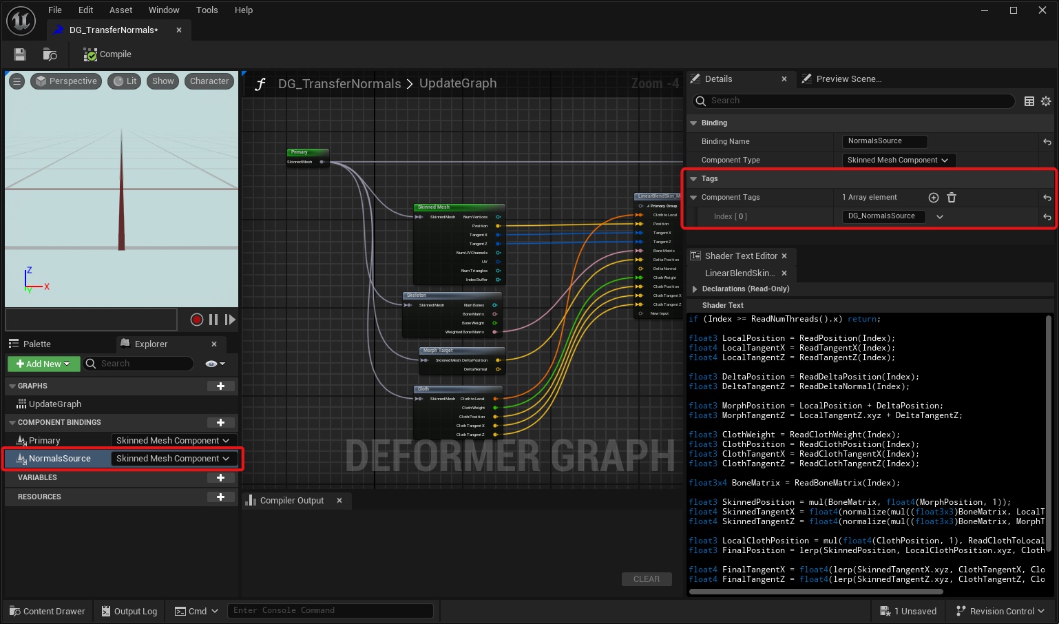
Let’s add a Component Binding. On the left side of the window, click the + button next to Component Bindings to add a new “Skinned Mesh Component”.
Name it “NormalsSource”.
Next, we’ll assign a Component Tag to NormalsSource. Select NormalsSource, then on the right side of the window in “Details”, add a Component Tag named “DG_NormalsSource”.
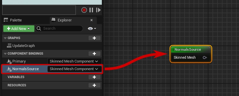
Add NormalsSource as an input node in the graph by dragging it from the panel on the left.
Get Data from the Component Binding
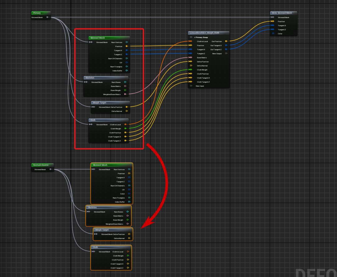
Just like the “Primary” mesh, we need to pull data out of the NormalsSource mesh. To do-so, copy the “Skinned Mesh”, “Skeleton”, “Morph Target”, and “Cloth” nodes and paste duplicates for NormalsSource.
Connect the pin from NormalsSource to the four nodes. We will use these nodes later.
Duplicate the Custom Kernel Node
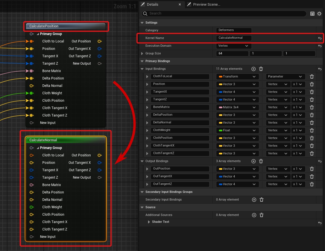
Select the “LinearBlendSkin_Morph_Cloth” node, then copy and paste it to the graph. We’re going to modify both of these nodes to split up the logic.
Select the nodes and rename them to “CalculatePosition” and “CalculateNormal”.
Setup CalculatePosition Node
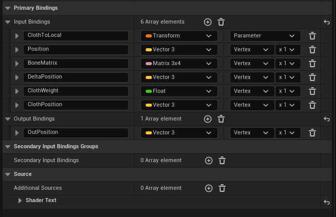
Select the CalculatePosition node. We’re going to remove the Inputs and Outputs we don’t need from this node.
In the Details panel, inside Primary Bindings, delete all but the following Inputs:
And delete all but the OutPosition Output:
Next we’re going to modify the HLSL code. This is a simple edit; we just need to delete the lines of code related to tangents.
Here is the final code for this node:
if (Index >= ReadNumThreads().x) return;

float3 LocalPosition = ReadPosition(Index);

float3 DeltaPosition = ReadDeltaPosition(Index);

float3 MorphPosition = LocalPosition + DeltaPosition;

float3 ClothWeight = ReadClothWeight(Index);
float3 ClothPosition = ReadClothPosition(Index);

float3x4 BoneMatrix = ReadBoneMatrix(Index);

float3 SkinnedPosition = mul(BoneMatrix, float4(MorphPosition, 1));

float3 LocalClothPosition = mul(float4(ClothPosition, 1), ReadClothToLocal()).xyz;
float3 FinalPosition = lerp(SkinnedPosition, LocalClothPosition.xyz, ClothWeight);

WriteOutPosition(Index, FinalPosition);
Setup CalculateNormal Node
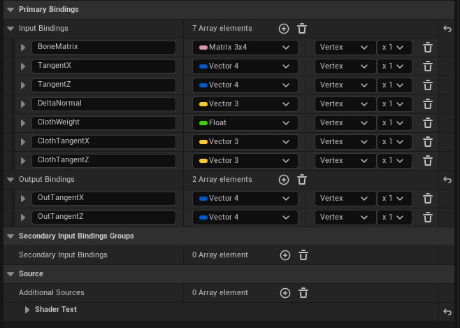
Select the CalculateNormal node. Just like the last node, we’re going to remove the Inputs and Outputs we don’t need and modify the HLSL code. But this time we’re keeping the logic for tangents and removing logic for position.
In the Details panel, inside Primary Bindings, delete all but the following Inputs:
And delete all but the following Outputs:
Next, modify the HLSL code. Delete all the lines related to position calculation, and just keep the lines for tangent calculation.
Here is the final code for this node:
if (Index >= ReadNumThreads().x) return;

float4 LocalTangentX = ReadTangentX(Index);
float4 LocalTangentZ = ReadTangentZ(Index);

float3 DeltaTangentZ = ReadDeltaNormal(Index);

float3 MorphTangentZ = LocalTangentZ.xyz + DeltaTangentZ;

float3 ClothWeight = ReadClothWeight(Index);
float3 ClothTangentX = ReadClothTangentX(Index);
float3 ClothTangentZ = ReadClothTangentZ(Index);

float3x4 BoneMatrix = ReadBoneMatrix(Index);

float4 SkinnedTangentX = float4(normalize(mul((float3x3)BoneMatrix, LocalTangentX.xyz)), LocalTangentX.w);
float4 SkinnedTangentZ = float4(normalize(mul((float3x3)BoneMatrix, MorphTangentZ.xyz)), LocalTangentZ.w);

float4 FinalTangentX = float4(lerp(SkinnedTangentX.xyz, ClothTangentX, ClothWeight), SkinnedTangentX.w);
float4 FinalTangentZ = float4(lerp(SkinnedTangentZ.xyz, ClothTangentZ, ClothWeight), SkinnedTangentZ.w);

WriteOutTangentX(Index, FinalTangentX);
WriteOutTangentZ(Index, FinalTangentZ);
Connect CalculatePosition and CalculateNormals
Now we can connect our two Kernel Nodes to the graph. We need to pass in the relevant data from each mesh to the Kernel Nodes.
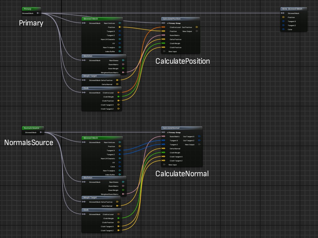
If you have trouble remembering which variable goes to what input, you can always reference the original Deformer Graph we started from (DG_LinearBlendSkin_Morph_Cloth).
Create TransferNormal node
We need to make one more Kernel Node, which will transfer the calculated normal to the Primary mesh.
If you were to try and plug in the outputs from CalculateNormal directly into the "Write Skinned Mesh" node, an error would occur upon compiling the graph.
In order for one Component Binding to affect another, we need to pass them both into one Kernel Node.
Copy the CalculateNormal node, and rename it to TransferNormal.
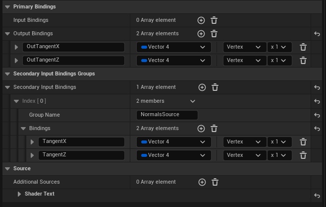
Delete all Inputs for the node.
This node needs to take inputs from NormalsSource, and output to the Primary mesh. To do this we need to use a “Secondary Input Binding Group”. This is how the Kernal Node distinguishes data from one mesh from another.
Add a Secondary Input Binding by clicking the + button under the Secondary Input Bindings Groups section.
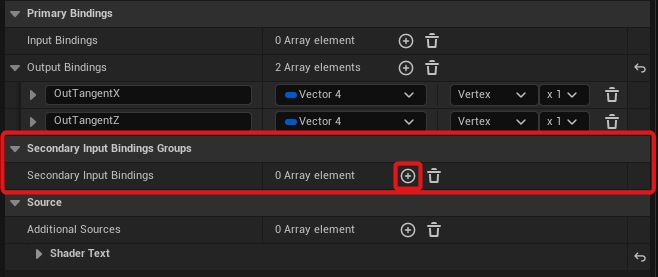
Expand the entry, and set the Group Name to “NormalsSource”. Then add the following inputs:
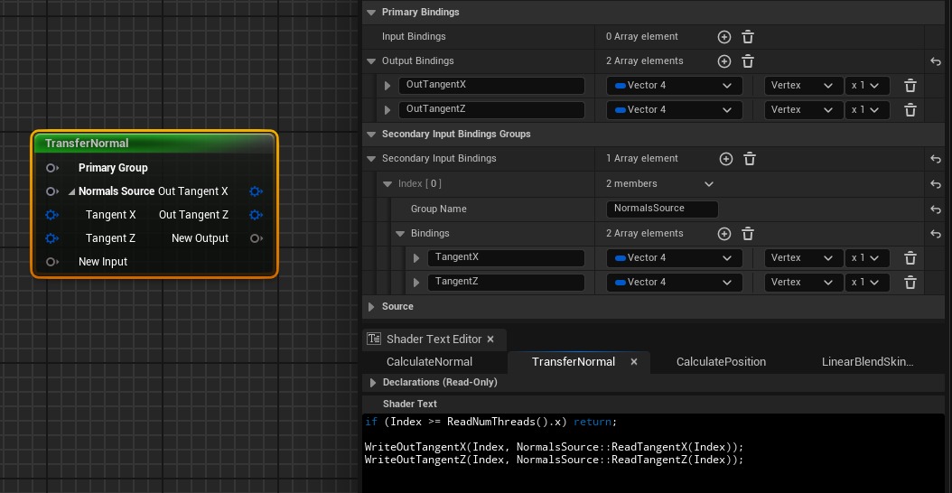
Write TransferNormal HLSL Code
The code for the TransferNormal node is very simple, but there’s one concept to understand first. In order to read inputs from the Secondary Input Binding (the one we named “NormalsSource”), we have to use the following syntax:
// NormalsSource:: before input read function
NormalsSource::ReadTangentX(Index);
With that in mind, here is the final code for this node:
if (Index >= ReadNumThreads().x) return;

WriteOutTangentX(Index, NormalsSource::ReadTangentX(Index));
WriteOutTangentZ(Index, NormalsSource::ReadTangentZ(Index));
This one couldn’t be simpler. It reads the tangents from the secondary binding, and writes it to the primary binding.
This code works because we assume the two meshes are identical. The vertex indices between both meshes will match, and therefore transfering the data is a 1-to-1 operation.
Here is one last look at the final node:
Final Connections of the Graph
We can now hook up our TransferNormal node to the graph and make the final node connections.
On the TransferNormal node:
- The Primary mesh connects to “Primary Group”
- The NormalsSource mesh connects to “NormalsSource”
- The outputs of CalculateNormal connect to the inputs of TransferNormal
- The outputs of TransferNormal connect to the “Write Skinned Mesh” node
We also connect the output of CalculatePosition to the “Write Skinned Mesh” node
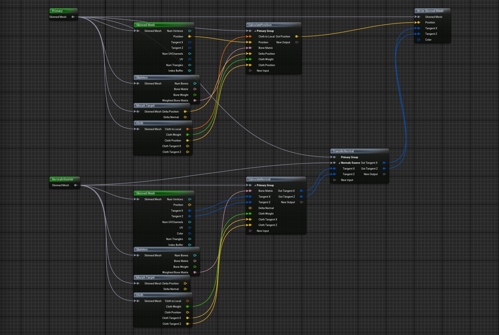
Compile the graph, and save it.
Using the Graph on a Skeletal Mesh
To use our normal transfering Deformer Graph, we need to use an Actor with multiple Skeletal Mesh Components (both of which use the same model).
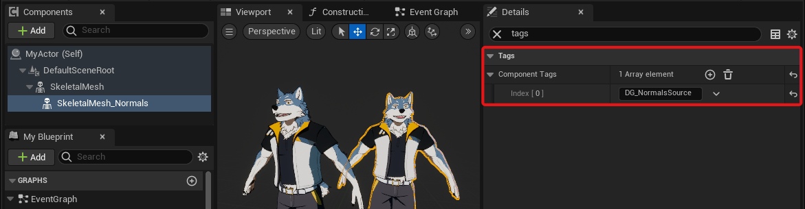
In your actor, select the Skeletal Mesh you wish to see, search for “deformer” in the Details panel, and set it to our new graph.
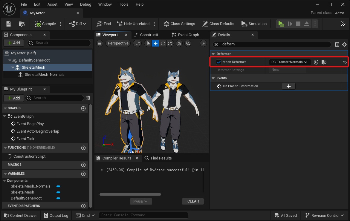
Then select the Skeletal Mesh you wish to transfer normals from, search for “tags” in the Details panel, and add the Component Tag “DG_NormalsSource”.
You will also (presumably) not want this second mesh to be visible. Setting its “Visible” property false will prevent it from working. You will instead need to create an invisible material, and override its material with it.
If everything was set up correctly, the normal transfering will now work!
Obviously, transfering normals is only useful if the other mesh has different normals.
The way I use this feature is to avoid bad normals caused by a character's physics asset. I make the second mesh have no physics, so that it transfers clean normals unaffected by any jiggling parts
Bonus - Transfer Normals Without Morph Target Normals
This is a bonus third Deformer Graph! You may find it useful to combine both of these techniques into one – transfer normals between meshes, and also ignore morph target normals.
If you’ve read this far, you should have the knowledge you need to accomplish this. We simply need to:
- Duplicate our DG_TransferNormals Deformer Graph (we can save it as DG_TransferNormals_ExcludeMorphTargets)
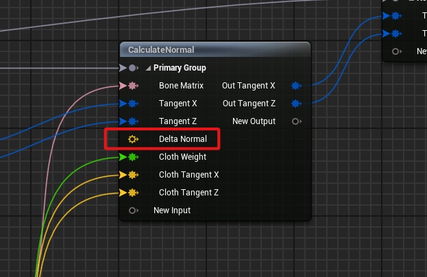
- On the CalculateNormal node, disconnect the input into “Delta Normal”
Final Thoughts
These two techniques are extremely useful for non-photo-real (NPR) characters in Unreal.
The first technique, ignoring Morph Target normals, is especially critical for anime style characters. In fact, Unity’s FBX importer supports this natively, a feature which Unreal’s importer sorely lacks. This has been a major roadblock for anime characters in Unreal.
Deformer Graph appears to be a powerful and performant solution for stylized characters. This guide is the result of my first experiments with it, and I hope it leads you to creating more cool features!
More Information on Deformer Graphs
For more information on Deformer Graphs I recommend the following:
Epic’s official documentation: link 1, link 2
Dilly’s Unreal Engine notes: link